


The version 2.1.0 of the plugin provides a new interface that better integrates in QGIS: two movable docks (or panels) for the ROI creation and the classification process; also, a main plugin interface contains several tools for expediting ROI creation, image post processing and advanced plugin settings.
For information about plugin installation and configuration see here.
At the end of this post you can find the video of this tutorial.
In this tutorial we are going to classify a Landsat image (single band rasters). Download the sample dataset from here, which is a Landsat 8 image (a subset acquired in the South of Rome, Italy) available from the U.S. Geological Survey.
The following bands (each band is a single 16 bit raster) are included in the file:
- 2 - Blue;
- 3 - Green;
- 4 - Red;
- 5 - Near-Infrared;
- 6 - Short Wavelength Infrared 1;
- 7 - Short Wavelength Infrared 2.
- Define the inputs
Required inputs are a multi band raster or single band rasters, and a training shapefile for ROI creation. In this tutorial we are going to create a band set.
- Start QGIS and load the raster bands; create a color composite (RGB=543) of the sample data, which is useful for the photo interpretation, as explained here (point 2); start the Semi-Automatic Classification Plugin (if the docks of the are not displayed, click the button Show docks in the main plugin interface);

- In the plugin dock ROI creation click the button Band set beside Select an image; the tab Band set will open; click the button Select All, then Add rasters to set; under Band set definition, order the band names in ascending order, from top to bottom using ? and ? arrows (this is useful for the interpretation of spectral signatures);

- Now we need to create a training shapefile that will store ROIs (a polygon layer that requires two fields ID_class and ROI_info in the attribute table); in the dock ROI creation click the button New shapefile, and select where to save the shapefile (for instance ROI.shp).

Hint: in order to use any shapefile (having different field names for ID and Information) as training shapefile, it is possible to change the default field names in the tab Settings of the main interface, according to the existing field names. When needed, the plugin will add automatically other fields for the spectral signature calculation.
![]()

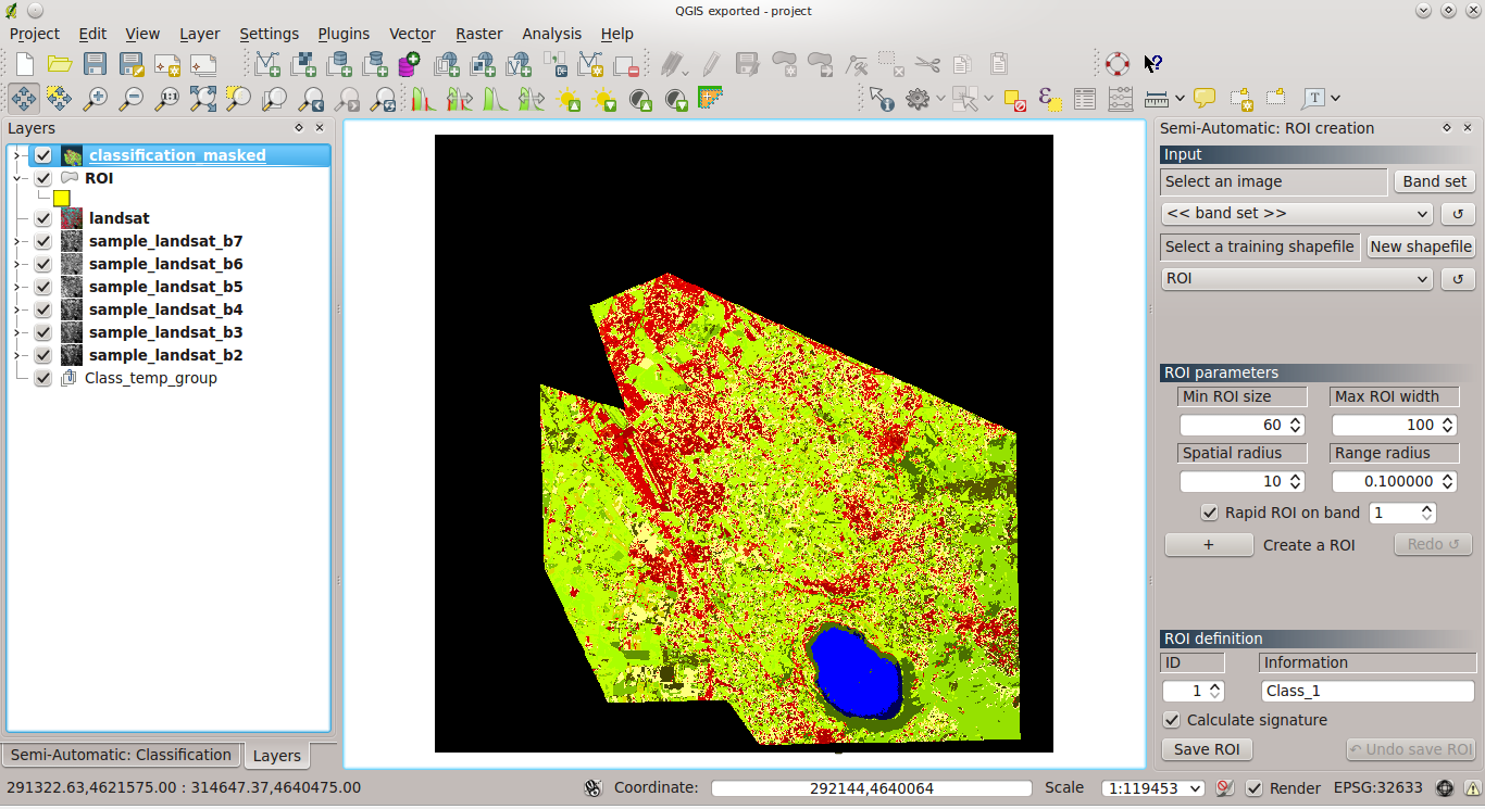
- Create ROIs
ROIs are polygons delimiting a certain land cover class, which are required to train the classification algorithm. Created ROIs are temporary polygons, which are placed inside the group Class_temp_group (added automatically if missing) in the Layers panel. This group should be moved to the bottom of the Layers panel; this way, only the last created ROI will be displayed over the image (the previous ROIs will be automatically hidden). - In order to create a ROI, in the dock ROI creation click the button + beside Create a ROI (this activates the ROI pointer); ROIs are created by clicking on any pixel of the image; click on the dark area in the South, which is the Lake Albano (use the mouse scroll to zoom); after a few seconds the ROI polygon will appear over the image (a semitransparent orange polygon);

- It is possible to change the ROI creation parameters, in order to create a smaller or lager ROI; change the Min ROI size value to 100, and the Max ROI width value to 150; in order to create a ROI at the same point clicked before, click the button Redo ROI;

- Now, check Rapid ROI on band and click the button Redo ROI; this way, ROIs can be computed only on one selected band, saving time especially for hyperspectral images; change the value to 4 beside Rapid ROI on band, and click the button Redo ROI; as you can see, ROIs have different shapes depending on the selected band;

- Open the Settings tab of the main interface; under ROI style it is possible to change colour and transparency of created ROIs as you wish.

- Save the ROIs to shapefile
This step is required in order to save the created ROIs to the training shapefile. - Under ROI definition type a brief description of the ROI inside the field Information (e.g. water); this description will not be used during the classification process, but it is useful for distinguishing ROIs; the field ID (i.e. identifier of the class) is used as reference for the land cover classification, therefore it is important that each category has a unique ID value; ROIs sharing the same ID are treated as a single ROI; now, leave the ID set to 1;
- If the checkbox Calculate signature is checked, then the ROI spectral signature is calculated while the ROI is saved; now, uncheck this checkbox (we are going to calculate it later, from the Spectral signature tab);
- In order to save the ROI to the training shapefile click the button Save ROI to shapefile;
- It is possible to delete the last saved ROI by clicking Undo save ROI.

- Spectral signature plot
- In the plugin main interface, select the tab ROI tools > Spectral signature, which displays the plots of selected ROIs, and select the item water; it is possible to calculate the ROI signature by clicking the button Calculate signature and confirming;
- If the checkox Plot s is checked, then the plot will display the standard deviation of each ROI; you can pan and zoom through the plot using the navigation toolbar (provided by Matplotlib).

Hint: in the tab Settings of the main interface, it is possible to change the maximum number of characters for ROIs of the plot legend (which is 15 by default).
![]()

- Multiple ROI creation at once
- It is possible to create automatically ROIs given a list of point coordinates (X, Y), class ID and ROI information (ROIs are created with the parameters defined in the dock ROI creation); select the ROI tools tab > Multiple ROI creation and click Add point to add a new line where you can fill the required fields; now select the line (click the line number on the left) and click Remove highlighted points;

- It is also possible to import a list of points, maybe from field survey; download this text file from here, click the button Import and select the downloaded file;

- In order to create and save the ROIs to the shapefile click Create and save ROIs (it takes some time, depending on the number of points).

- Perform a classification preview
Classification preview is a rapid way to evaluate collected ROIs.
- It is possible to choose between several classification algorithms (Maximum Likelihood; Minimum Distance; Spectral Angle Mapping); now select Spectral Angle Mapping;
- Algorithm threshold allows you to leave unclassified pixels that meet a certain rule: for Maximum Likelihood, pixels are unclassified if probability is less than threshold (max 100); for Minimum Distance, pixels are unclassified if distance is greater than threshold; for Spectral Angle Mapping, pixels are unclassified if spectral angle distance is greater than threshold (max 90);
- Preview size is the side of the classification preview (in pixel unit); set Size to 300; click the button + under Classification preview and click on the image; similarly to the ROI, click the button Redo to perform another classification preview at the same point;

- Created ROIs are displayed in the ROI list; double click on any item to zoom to the corresponding ROI in the map; also, it is possible to delete selected ROIs using the button Delete selected ROIs.

- Set a classification style
It is useful to create a classification style with labels that will be loaded for every classification.
- In the panel Layers, left click on a classification preview and select Properties; change the colours and labels of classes, according to the training ROIs; then, create click Save style ... to save the .qml file (e.g. style.qml);

- In the Classification dock, under Classification style click the button Select qml to select the file style.qml; the next classification will be loaded with this style.

Hint: after adding a new class to the training shapefile, repeat the above steps to overwrite the .qml file and update the classification style.
A large number of ROIs is required for a good classification. Download this training shapefile from here, which contains several ROIs, and load it in QGIS.
- Classification output and options
- The main output of a classification is a raster file .tif; click the button Perform classification and select where to save the output (e.g. classification.tif); use the classification style from the file zip that you can download here;

- In addition to this raster, it possible to create a shapefile of the classification by checking the checkbox Create vector; the shapefile will be saved with the same name and in the same directory of the .tif file (it takes some minutes for the vector creation, depending on your system spec);

- If the checkbox Calculate accuracy is checked, than the error matrix is calculated and saved as file .txt in the same directory of the .tif file (also, it is automatically displayed in the tab of the plugin main interface Post processing > Accuracy); the error matrix is calculated by comparing the classification to the training shapefile used for the classification (see below Post processing tools);
- It is possible to apply a mask shapefile to the classification; download this shapefile from here, check the checkbox Apply mask and select the downloaded shapefile; click the button Perform classification, and the classification will be saved along with the error matrix and the vector output.
- Post processing tools
- It is possible to assess the classification accuracy (implemented by GRASS GIS), by comparing the classification to a reference shapefile (not necessarily the training shapefile); now, select the tab Post processing > Accuracy of the plugin main interface; select the classification.tif beside Select a classification to assess and select the ROI shapefile beside Select the reference shapefile; then click the button Calculate error matrix and the matrix will be displayed; you can save the error matrix by clicking the button Save error matrix to file;

- It is useful to calculate the land cover change (through GDAL and Numpy) between a reference classification raster and a new classification raster; download this classification from here (pretend this is the last year classification); select the tab Post processing > Land cover change of the plugin main interface, select the downloaded classification as reference classification, and the classification.tif as the new classification; click the button Calculate land cover change and select where to save the raster of changes and the related table (i.e. a file .csv, whose values are separated by tab); pixel values of the raster of changes (ChangeCode) are described in the table, and each value represent a class of change from the reference classification to the new classification;


- If the checkbox Mask unchanged pixel is checked, then unchanged pixels will have a value of 0 (Unclassified).


- In the tab Settings of the plugin main interface it is possible to set the RAM used for processing; set the Available RAM according to your computer spec (in general, half of the system RAM is a good value);
- The tab Settings provides some features for debugging:
- if the checkbox Record events in a Log file is checked a Log file is created and updated during the processes; the Log file is saved in the plugin directory (located inside your user/home directory, .qgis2/python/plugins/SemiAutomaticClassificationPlugin), with the name __0semiautomaticclass.log;
- several buttons allow for the testing of program installation such as: SAGA GIS, Orfeo Toolbox, GRASS GIS, and QGIS geoalgorithms;

- If you experience any issue when running the plugin:
- activate the recording of the Log file;
- restart QGIS;
- test the installation of required GIS programs;
- perform the same steps that cause the issue;
- open a ticket here, describing the issue, and attach the Log file.
I hope that the new features will enhance the classification experience in QGIS; however, any feedback is highly appreciated. Please note that QGIS 2.0 is still under development, therefore some changes could affect the plugin until the final version is released.
The following is the video of this tutorial.
The following is the video of this tutorial.